I have been a big fan of spring and plate reverbs for decades, and over the past three years I have spent a significant amount of time diving into the wormhole of designing and building them, initially for my own use and now for others. There are many amazing vintage units in existence, but I wanted to design one around current, commercially available reverb tanks, as not to be at the mercy of sourcing old parts. Recently my custom shop has been offering the result of this research: the SR4, a four-tank unit with a plethora of features. For this article, I took the basics of the SR4 and reduced it down to the simplest design I could come up with to share with the DIY audio community.
Simplified Reverb Tank Overview
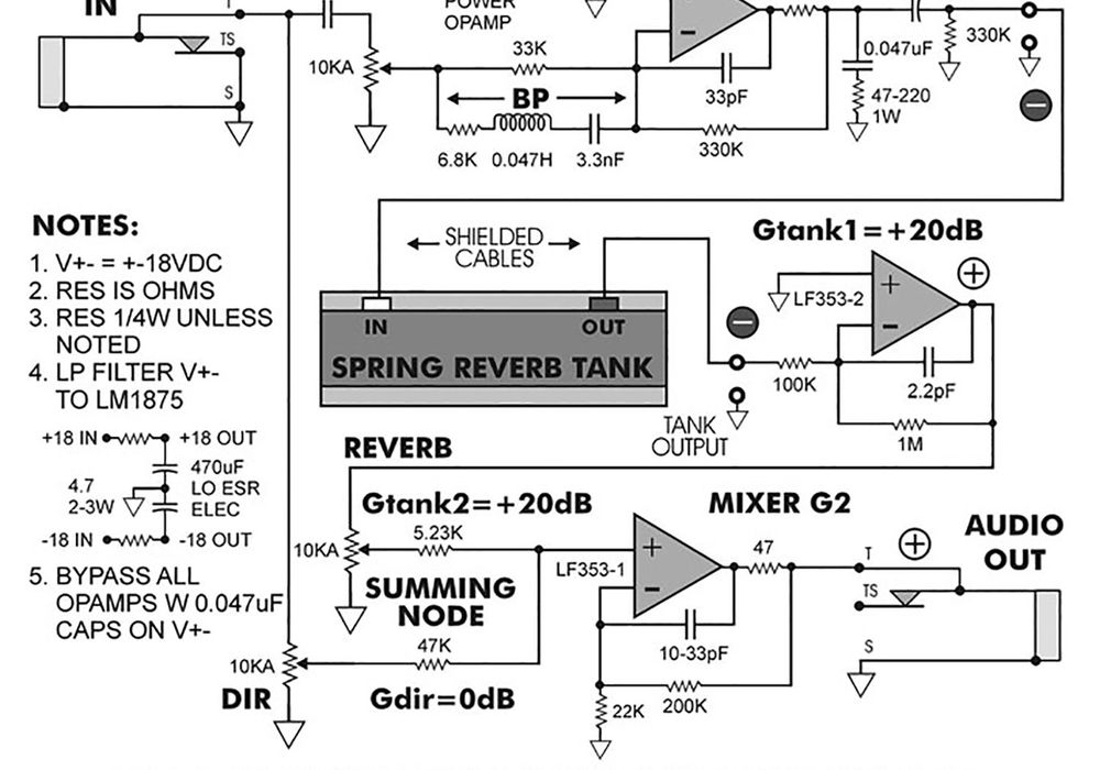
A modern reverb tank consists of drivers, transmission springs, pickups, and a shock mounting system. A signal is driven into the drivers (attached to one end of each spring, labeled “input”), which acts like a speaker; but instead of moving air, it modulates the springs. The opposite end of each spring is attached to a pickup, which converts the vibration of the spring into a small current/voltage (depending on how you look at it in the circuit). Each spring has a damper disk, which does as its name implies, damping the spring to shorten the decay time and control the modulation. The pickups share a common core (similar to a transformer) so their outputs are summed. Typical tanks have two or three springs, which are usually slightly different to provide a richer, denser sound. Each transmission spring may be divided, further creating complexity in the reverb. The mechanical properties of the springs determines the decay/reverb characteristics. Tanks also have a wide range of input and output impedances.
If you are replacing one, it is important to get these as close to what the original one was in order to ensure they are driven, and amplified correctly.

Driving Reverb Tanks
Accutronics/Belton (now Accu-Bell Sound Inc.), the popular manufacturer of spring reverb tanks, states on their website, “First and foremost, the point to remember is to drive the unit as hard as practical. The core saturation level is approximately 2.5 A-T (amps measured RMS [Root-Mean-Square]). The driver, at maximum expected input level, should drive the coil to near saturation. This is of utmost importance in applications where a speaker is mounted in the same enclosure as the reverb, such as a guitar amp or organ. This will allow the output, or recovery amplifier gain, to be reduced, lowering possibilities of feedback and minimizing microphonics.” Basically, they are saying you need to drive the tank hard to get maximum output. The current is limited by the power supply rails, divided by the tank Zin. Tanks with low Zin (8-16 ohms) need a lot of current, whereas tanks with a high Zin (1-3 kohms) need high voltage rails (i.e., tube amps). I’ve found that tanks with intermediate Zin (50-300 ohms) were a good choice for typical +-15<->24 VDC rails, where a reasonable amount of power can be delivered without either high current or high voltage power supplies.
Input Impedance
Unlike driving a speaker, the drive signal to a reverb tank is ideally not flat, with respect to frequency. Accu-Bell specifies that the signal should rise 6 dB per octave to deliver constant current over the frequency range, or to use a constant current driver circuit. This reason is due to the fact that the input impedance has both resistance and inductance, making the Zin increase linearly with respect to frequency, once the reactive part XL becomes much larger than R.
Zin = R + XL
R = DC resistance (what an ohm meter will measure)
XL = i2*PI*F*L, where “i” indicates phase angle
(i.e. imaginary)
Other parasitics (like capacitance) exist, but are omitted for simplification as they are beyond the scope of this DIY application. It is important to note the “i” term means (in this case) phase angle of 90, so the two numbers (R and XL) can’t simply be added, they must be summed using vector math. The reason this is important is it will determine how much current/power you are driving the input with at the peak frequency of the drive circuit. If the tank is driven with a flat response, the drive current decreases linearly versus frequency, because Zin increases and the result is the reverb sounds dark and muddy: I = V/Zin
I spent a few days testing several tanks to see how closely the tanks behaved to the equations for Zin (R+XL). Are there parasitic impedances, or electro mechanical effects that make the input impedance change in a way different than the simple math? Using CPU-controlled test equipment (two high-resolution volt meters and a phase meter), I set up a test to measure the complex input impedance of various tanks versus frequency. I then measured...