Back in July/August of 2002, I offered up a tube mic preamp circuit here in Tape Op, and provided a kit for a limited time to assist in building it, through my company Hamptone. For all of you I scared off with subtle warnings about hi voltage and serious death, this project may be more your speed. My goal was to design an extremely simple solid-state circuit that sounded great, but was inexpensive and easy to build. Tube circuits inherently get more complicated because of power supply requirements, whereas the circuits shown here can all be run off a DC wall wart. First I will describe how a JFET (junction field effect transistor) works and why I chose it as the amplifying device. Second, I will show a circuit implementing the JFET in a simple class A gain stage with a voltage follower. Last, we will use the gain stage in three applications: an instrument preamplifier, a microphone preamplifier, and a line mixer. The JFET amp shown here can be applied to a variety of other applications including condenser microphones. It will be my intent to keep this more oriented toward practical application rather than going heavily into technical detail. So fire up your soldering irons, let's DIY!
THE SOLID STATE TUBE:
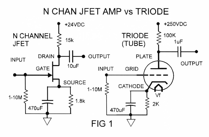
Figure 1 shows two class A amplifiers, one designed with an N channel JFET, the other a triode vacuum tube. Though the supply voltage and some component values are different, the overall circuits are identical. In fact, the N channel JFET behaves like a triode; a voltage controlled current source (or sink in this circuit). A change in voltage on the gate, produces a change in current through the drain. This change in current across the 15k resistor results in a voltage that is an amplified version of the input, and out of phase. In contrast, a transistor is a current controlled current source. By nature, JFETs and triodes have a very high input impedance, meaning they require almost no current to drive their inputs. JFETs also saturate in a soft way very similar to triodes. When listening to the JFET circuit side by side the equivalent triode circuit (with the same transformers), it's surprising how similar they sound. The tube circuit has more headroom, and a bigger presence in the bottom end, but the JFET amp is very clean in the upper end, and has a very flat and tight low end. I actually like it better than the tube circuit as a bass DI (if forced to go direct). With the proper gain structure on the front end, the JFET amplifier can deliver a very accurate and musical sound. The fun starts when you overdrive the shit out of it. The distortion characteristics of the JFET based mic preamp are just as useful (if not more) than its merit as a clean and accurate mic preamp. And jumpering one JFET mic preamp into another, and working the two pads and volume controls, unleashes a palette of sonic evil.

JFET GAIN MODULE:
Figure 2 shows the 2N5457 N channel JFET circuit in figure 1 with an output stage added. The signal is applied to the gate of the JFET, and the output is taken off the Drain (amplified and inverted in phase). A 50-ohm resistor has been added that is not bypassed by the 470 μf cap, which reduces the third harmonic by about 20dB. The NPN transistors act as a voltage follower providing the output drive, with near unity gain. The dc voltage on the drain is slightly above the supply, and directly biases the MPSA14 Darlington transistor. A Darlington is used to minimize the loading on the 2N5457 (Darlington transistors have a much higher input impedance). The ZTX653 is a generic NPN transistor acting as an active load (beta = 100 min). Since the output also has roughly 1/2 the supply voltage on it, a coupling capacitor on the output is required to block the DC but allow the audio signal to pass. This is a key component and worth a few extra bucks for a good quality polypropylene capacitor or better.
The output impedance of the voltage follower is a function of the 47 kilo-ohm resistor on the base of the ZTX653. If this resistor is too big, the output will not have enough drive and will be clipped on one 1/2 of the waveform. On the opposite end of the spectrum, if you make it too small, more power will be dissipated than is needed in the output devices. The value shown provides adequate drive for typical line inputs, with or without the 1:1 output transformer.
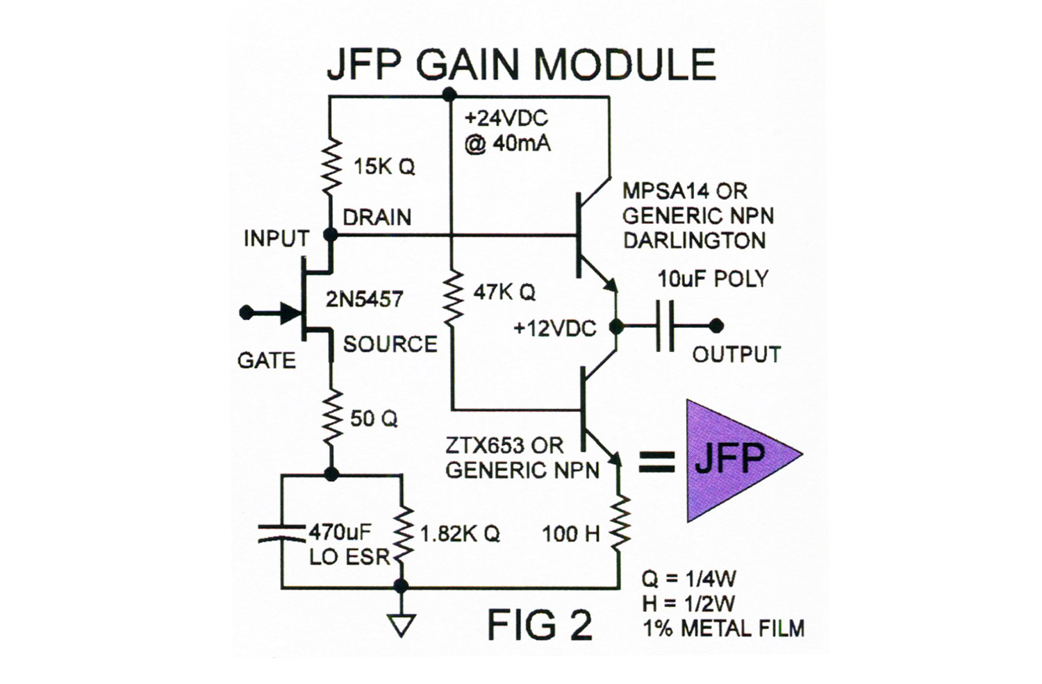
There are as many ways to buffer a signal as there are signals, so I leave it up to the reader to explore more esoteric designs if desired. The one shown here works great, and in my opinion is not compromised in any way just because of its simplicity. This circuit (figure 2) will from here on be referred to as the JFP (JFET preamp) and represented by the purple triangle. The input impedance of the JFP is basically the value of resistance on the gate to ground, and can be as high as 1000Mohms. The gain is approximately +26 dB, with the signal at the output being...