WORDS OF WARNING
To build this unit requires a fair amount of experience as a DIY-er. In addition, this circuit requires voltages that can cause serious death if mishandled. The kit greatly simplifies the assembly and possibility of mis- wiring, but still can be dangerous if care is not taken. You should be comfortable around high voltage electricity. The audio path of this design is really quite simple and could be point-to-point wired in a few hours. The power supplies are a bit more complicated, but off the shelf regulator part numbers are provided.
CHANNEL DESCRIPTION
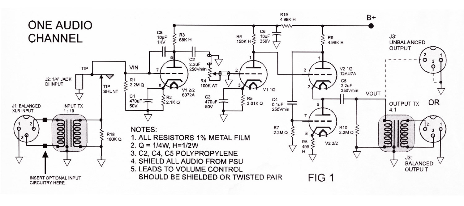
Referring to Figure 1, the amp is basically two gain stages (the two halves of the 6072/12AY7A) separated by a volume control, with a buffer after the second stage to drive the output transformer. The first stage has about 28 dB of gain, while the second provides roughly 30 dB. The Totem Pole output follower (the two halves of the 12AU7A, R7, R8, R9, C4) has unity voltage gain and drops the output impedance down to about 700 ohms. The overall gain is +64 dB with input/output transformers, which is more than enough for low output ribbon mics. If more gain is required, a 12AX7A can be substituted for the 6072A, but the soft characteristics of the 6072A will be lost, and the preamp will sonically be far less forgiving. The 6072A/12AY7A has a very soft roll-over, and generates almost no odd harmonics when biased properly — making it, in my opinion, the choice for the gain stages. It should be noted that the circuit works fine without the output transformer if a balanced signal is not required and cable runs are not long. The output transformer is a step-down (4:1), and will drop the amplifiers overall gain by -12 dB. Without it, the amp will have more headroom, but will lose some of the desirable tube compression characteristics because the second gain stage will not be driven as hard for the same output level. For the prototype, I used Altec 15095A line transformers that I got on eBay for about $20 each. These transformers, when used as a step-down, work very nice for the money. Probably the most important component is the input transformer — I would highly recommend not skimping here. If you are going to make compromises, don't do it on the front end. The Jensen JT- 115k cost about $65 each and sound great, though any 1:10 step-up input transformer with proper mic input impedance would work. Refer to my website for other transformer options. I tried using an Altec 4722 as an input transformer, but found they have very poor phase response past 10 kHz. If money is an issue, the amp still works as a nice tube DI without the input transformer.

OPTIONAL INPUT CIRCUITRY
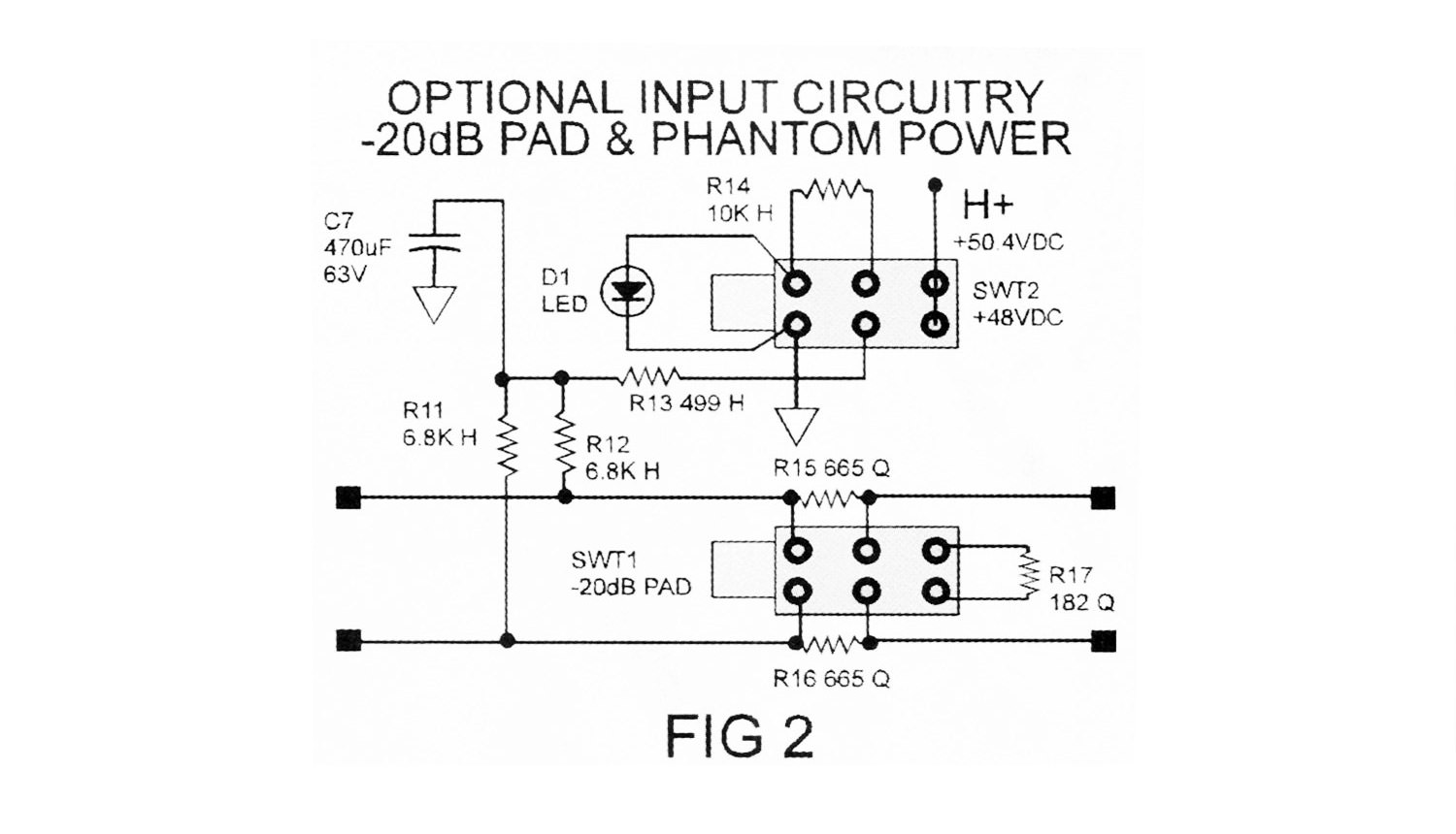
Figure 2 shows optional input circuitry that would be inserted before the input transformer, providing a 20 dB pad, and phantom power. R13 and C7 are optional, comprising a "pop" reduction filter when the phantom power is turned on, as well as extra filtering on the +48 volts being provided to the mic. The pad maintains the proper impedance between the mic and transformer while reducing the signal by 20 dB. Under most circumstances the pad won't be needed, as the amp and input transformer have a lot of headroom, and driving the first gain stage harder usually sounds good. Also the noise figure of the amp is degraded when the pad is activated. I put it in the design mostly because some people will want it, and it's only 3 resistors and a DPDT switch.

POWER SUPPLIES
The power supplies for this design are somewhat flexible, and can be designed in a variety of ways. If you plan on building this without the kit, I would recommend buying off-the-shelf regulated supplies (see schematics for supplier and part numbers). The high voltage can run realistically anywhere from 150 vdc to 240 vdc (DO NOT EXCEED 250 vdc!), though this design is optimized for 225 vdc. The filaments of the tubes require 6.3 vdc @ 300 mA each if wired in parallel or 12.6 vdc @ 150 mA each if wired in series. Phantom power is +48 vdc @ 50 mA. For the prototype, I designed the filament supply with a regulated +50.4 vdc @250 mA. If you connect all the tube heaters for a two-channel unit (i.e. 4 tubes) in series, you get 50.4 vdc. This eliminates the need for a separate phantom power supply. It also minimizes power dissipation in the filament regulator because of the reduced current requirement as compared to that required if the tubes were wired in parallel. Making this a good clean regulated supply is important. The passive "pop" filtering on each channel (C7/R13) drops the 50.4 vdc down a volt or two (depending on the mic) for proper phantom power voltage, though running the phantom power a little high is not a problem if you choose to eliminate it.

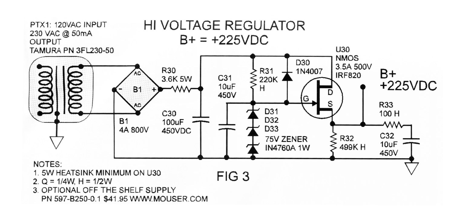
Figure 3 shows the +225 vdc Source Follower regulator. This circuit, under the required load, is very clean and simple to build. It works like this: The rectifier B1, R30, and C30 convert the 230 vac to a rough 260- 270 vdc (loaded value), with a few volts of AC ripple. Voltage is fed to the gate of the high voltage N channel mosfet through R31with a zener diode (actually 3 x 75 v = 225 v in series) to ground to set the output voltage. C31 and R31 act as a low pass filter and reduce the noise on the rough DC to a negligible amount. Because of the mosfet's high gate input impedance, the filtering can be heavy without much voltage drop across R31 other than that set by the zener diodes, which would be the case if a transistor were used. This means the mosfet will hold a constant output regardless of load (within a few volts DC). It is not a true 3 terminal design, but I felt this circuit worked adequately, and has about 1/3 the components of a truly regulated design. R33 in series with C32 on the output cap is essential, otherwise the unit oscillates during power up. The drain of the mosfet is tied to the rough 260-270 vdc, while the source is the output. You can generate a high voltage DC supply with "brute force" by eliminating the mosfet and simply having several RC stages to reduce the noise (like R30/C30). Though this design may seem more simple, it actually costs more (i.e. expensive hi voltage caps, mosfets are about $1) — plus the output is unregulated so the voltage will be a direct function of current. It also takes up more physical space (for equal AC out) and is generally noisier. Additionally, the output impedance of the "brute force" design is higher, which can adversely effect transient response of the audio amps, though some people like the sound of a "sagging" supply.
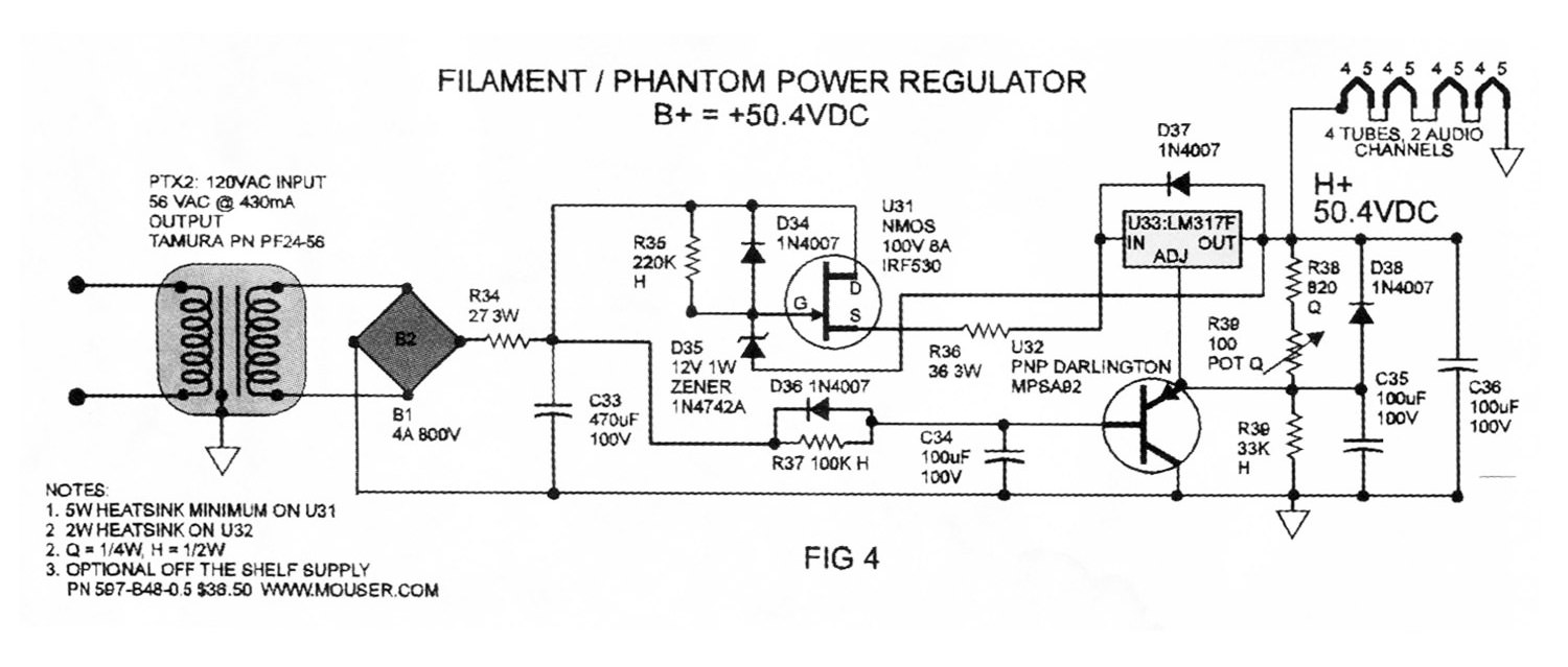
Figure 4 shows the +50.4 vdc regulator. This regulator is not quite as simple, since this voltage needs to be very clean for the phantom power, and it needs to deliver more current than the high voltage. It employs a Source Follower pre-regulator, with a true 3 terminal regulator to precisely set the output voltage. In this circuit, the gate of the mosfet is tied to the output of the regulator through a zener diode. This sets the output of the mosfet to be above the regulator's output by (approximately) the value of the zener diode, in this case 12 vdc. The voltage across the regulator (and the power dissipation) is then fixed within a few volts. This protects the 3 terminal regulator from its input/output voltage exceeding the maximum rating (30 vdc) while minimizing its power dissipation (so the regulator operates cool/quiet). U32, the pnp transistor, provides a slow ramp-on feature which eliminates the problem of the 3 terminal regulator going into over current mode at power up. Tube filaments are a dynamic load in that their current consumption decreases as they warm up. If you slam the voltage on to the filament of some tubes, the current can spike up as much as 3 times the normal operating value until the tube warms up. When the AC power is turned on, the base of U33 is held at ground, saturating the transistor and pulling the adjust pin of the regulator to ground (the output is always 1.25 vdc above the adjust pin on the LM317F). As the voltage on the base of U32 charges up through R37/C34, it eventually shuts off, and the output of the regulator is governed by the ratio of resistors R37, R38, and R39. Again, if you are planning on building this without the kit, it would be advisable to simply buy the off-the-shelf regulator. For the money, it will reduce a lot of headaches. If you choose to use the printed circuit board (pcb) provided with the kit, you can save a bit on component cost, and the physical size is smaller than the open frame "off the shelf" unit.

MY PROTOTYPE
Figures 5 and 6 show the prototype unit I built of the design. The power supply and two audio channels are all located on a single pcb. The kit differs only in that the power supply is a separate pcb. What I found was that a shield needed to be between the power supply and audio electronics, otherwise the AC noise floor was unacceptable. So making the two boards separate will make it easier to keep the audio and power isolated. The audio connectors and switches for pad and phantom power are all on the pcb, which made assembly go very quickly, eliminating almost all the point-to-point wiring. Two units will fit in a 19" 3U rack box with room to spare (for 4 channels), though I preferred making my unit portable.
Sonically, when put up against mic pres in a much higher price bracket, this design holds its ground and has all the characteristics of a classic tube/transformer design. The bandwidth is about 6 Hz to 100 kHz, and with the pad out has a very acceptable noise floor. When driven hard, the harmonic content is very musical.

MODS/IMPROVEMENTS
As I stated earlier, this design is "borrowed" from my Silverbox4 tube mic pre. In the pursuit of sonic perfection, the cost to make small improvements exponentially increases as you push the limits. There is a point, though, where under a lot of circumstances, these subtle differences, which make the material cost per channel 5 times more, really don't make that big of a difference, if any. There are, however, a few things you can do to improve/modify the unit that will raise the price a bit, but are worth mentioning.
Step attenuators instead of volume pots. Purely resistive attenuators are far better than pots as they have far less reactance. The kit includes charts of resistor values for various step attenuator designs. These are also provided free on our website.

Add a totem pole follower after the first stage, before the volume control. This buffers the first stage, allowing the pot to be reduced from a 100 K to 5-10 K. Pots have reactance, the bigger the value of pot, the worse the effect on the audio signal. They can cause phase shift and dispersion if the value is too big (making the sound a bit "mushy"). In this design the first gain stage has to drive the pot without a buffer. Because of the higher output impedance of the first stage (compared to the totem pole), the 10 pF feedback capacitor is required on the first stage to keep it from oscillating at higher gain settings. If the first stage is buffered like the second, the cap can be removed for a slight sonic improvement in the top end.
Adjust the bias point, for fun. Changing R2 and R5 sets the "bias" of the two gain stages. Making these resistors bigger under-biases the amps, reducing gain and headroom. The benefit is the amp saturates very quickly and can sound really good on vocals/percussive signals. Making these resistors smaller takes the amp past the linear operating point and in general just makes it distort in a sonically displeasing way (lots of odd harmonics). The design shown under-biases the gain stages slightly from the optimum linear operating point. It's a good tradeoff point between accuracy and tube "color". The totem pole follower works best when the DC voltage going into the Grid of V2 (pin2), is roughly B+ / 2. So adjustments to R5 should be slight.
Double up capacitor types on caps in the signal path. A 0.01 uF 250 V polystyrene cap in parallel with C1, C2, C3, C4, and C5 reduces the dissipation factor/distortion of these caps. This has a subtle improvement in the high end. Also, making C5 bigger will make a slight improvement to the bottom end. The values of caps chosen however provides more than adequate bandwidth.
CONCLUSION
The main objective with this article was to provide a circuit for a very good sounding tube mic pre, at a reasonable price. Keep in mind that if you go to a store and buy a $400/$500 mic pre, probably only $100 is actual material cost. You simply get what you pay for. So by investing some "sweat equity" into building it for yourself, you will end up with something far beyond what you could get for the same price.


