Welcome to a very overdue installment of my geekish banter. Issues of Tape Op have been flying by without me and I thought it was about time I blessed you all with some more electro-quackery on guitar amplifiers, music electronics, and tenuously related subjects. You might remember the last time we met I explained how capacitors worked in your gear, and how you could change the filter capacitors in your guitar amplifier to beef things up a bit. This time I'd like to give the same treatment to resistors. In this column I'll illustrate what resistors are, what they do, how to identify them, and then offer some real-world tricks that will allow you to use resistors to soup up your amp a bit.
Disclaimers
#1: TAPE OP and I are not responsible if you kill your amplifier or yourself! Tube guitar amps carry enough voltage to kill you even when they are turned off and unplugged! Do not open up your amplifier unless you know how to discharge filter caps and have a good idea of what you are doing! NEVER open up your amplifier when it is plugged in!
#2: I'm no expert. I learned everything I know from reading and blowing shit up. I do not guarantee the accuracy of the information in this column and I welcome all additions and corrections.
Resistors are Everywhere
Even the casual geek knows that resistors are everywhere. They're the little color-coded tubular components that are a fundamental part of everything from your high-end mic preamps to your rack gear to your Roland Juno-106 and right down to your Tube Screamer. Even your silly looking G3 uses resistors, and in some cases, the tone controls on your guitar or bass as well. To gain an understanding of what they are and what they do, we need to take a minute (surprise) to revisit your high-school physics class, so bust out your Trapper Keepers.
Circuit Theory 101
You'll remember from high school (and from my previous two articles) the analogy of electricity as water that flows down the path of least resistance. To keep things simple, imagine that electricity flows across wires just like water flows through a pipe. We can imagine that there are three elements that control the flow of water through a pipe: the water pressure, the amount of water, and the size of the pipe. Likewise, the flow of electrons down a wire is dictated by the pressure (voltage) pulling the electrons, the amount of electrons (current), and the size and material of what the electrons are flowing through (resistance). A thick copper wire has very little resistance, but if we cut the wire and put a piece of carbon in the gap, we add resistance to the flow of electrons. This, just as if we put dirt and gravel in the middle of the water pipe, we impede the flow of the water. With me so far? No? Well, it's sort of like when the screen in your bong gets all clogged with resin and...
In any case, if everything else escaped you from Physics 101, you surely remember that Ohm's Law is best way to explain the relationship between these three elements-current, voltage, and resistance. Now, before you nod off or start carving Van Halen logos onto your desktop, take a minute to visualize this relationship. Ohm's Law can be thought of as the amount of current (in Amps, usually expressed as I for some stupid reason) in a circuit is equal to the voltage (volts, or V) divided by the amount of resistance (or R, expressed in Ohms). In geek form, this looks like I=V/R. As you also know from Algebra 1, you can express this equation in two other ways: V=IR and R=V/I. This simple equation allows you to figure out any one of the three factors in a circuit if you know the other two. So how much current is flowing through a wire with a 400 Volt power supply through 100 Ohm resistor? If you said 4 Amps, go to the head of the class.
What Resistors Do
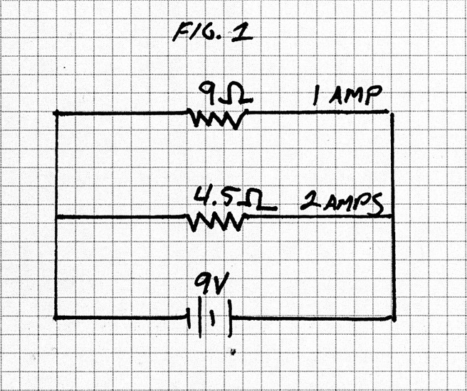
Although basic Ohm's Law has little value when you're poking around your gear wondering what's what, we can use it to understand how amplifiers (and other gear) actually use resistors. For the most part, resistors do two main jobs: limit current and divide voltage. For example, lets say you have a stompbox with a power supply of a 9-Volt battery. The design of the stomp box requires that you supply one point in the circuit with 1 Amp, and another point with 2 Amps. You can create this situation with resistors in parallel. As you can see in Figure 1, if we put two resistors in parallel with the 9-volt battery, we can split the current between them. We can use Ohm's law to figure out just what size resistors we need: if we know we need 1 Amp, we can use Ohm's Law to figure out that 9 volts divided by 1 Amp leaves us with a 9 Ohm resistor. Likewise, 9 Volts divided by 2 Amps leaves us with a 4.5 ohm resistance. Here we see that resistors in parallel act as current dividers, and that the voltage remains constant throughout the circuit.
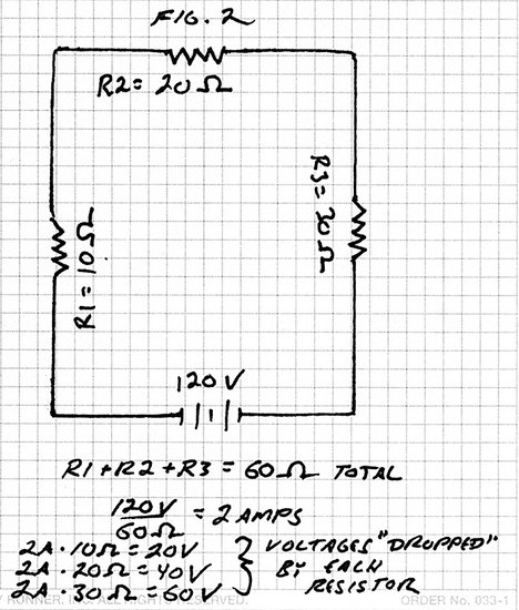
You can use similar logic to see that resistors in series act as voltage dividers. Consider figure 2. We have three resistors in series with 120 volts. The voltage between the the resistors is different from the voltage at the positive or negative lead of the battery because some of the voltage is dissipated by the resistance, just as water pressure is dissipated as it tries to push water through the clog in a pipe. The important thing to remember is that the current remains constant in this situation, just as the same amount of water still travels through the pipe, it just arrives at a slower rate and with less pressure then it began with. So, given the resistance values of 10 ohms, 20 ohms, and 30 ohms, figure 2 illustrates how we can figure out the voltages between the resistors, and the constant amount of current flowing through all of them.
Also, notice from these two examples that the Total resistance in a circuit with resistors in series is the two resistors added together, and the total resistance of a circuit with resistances in parallel is the resistances added and then divided by the amount of resistors. In other words, in a series circuit, R=R1+R2+R3 where there are three resistors in series and R is the total resistance.
In a parallel circuit, 1/R = 1/R1+1/R2+1/R3, where the circuit has three resistors in parallel and R is the total resistance. So, in figure one, the total resistance is a little less than 7 ohms (13.5/2), and in figure two the total resistance is 60 ohms.
This column just glosses the surface of circuit theory. You can use Ohm's Law to calculate the resistances, voltages, and currents in more complex circuits that have resistors in both parallel and series. If you're interested in learning more, any high school physics text will do. The purpose of this introduction is simply to illustrate how resistors do the job of dividing voltages and limit current in your amps and other audio gear. Next I'll show you how to recognize them and then a few ways you can manipulate them to beef up your Fender amp.
Recognizing Resistors
Unlike the obscure and proprietary markings on capacitors, most resistors are clearly color coded with an international standard that makes them easily identifiable. There are usually four color bands around the resistor that indicate its value and tolerance. The first band will usually either be silver or gold. This indicates the tolerance of the resistor. If the band is silver, the resistor is within 10% of it's indicated value. If it's gold, it's within 5% of its indicated value. Don't worry too much about the tolerance of the resistor. Usually 5% or 10% tolerances will work fine for most applications. (Sometimes resistors start with a red tolerance band, indicating they have a 2% tolerance. Others have no tolerance band at all, indicating a 20% tolerance. But for the most part, you'll find gold and silver bands on the resistors in your audio gear.)
The remaining three color bands indicate the actual value of the resistor. The following chart (sidebar) will help you decode the values.
Starting from the tolerance band, the second and third bands indicate the first two numbers in the value, and the final band indicates the number of zeros that follow. So, for example, if you see a resistor that has a silver, blue, gray, and brown stripe, it has the value of 680 ohms and it has a tolerance of 10%. One thing you should know to make this easier is that for most gear you'll usually be using only a few values over and over again. In Fender amps there are usually no more than 10 or 15 different values for the most part, so you don't have to spend all your time decoding values. Also, when you buy resistors at Radio Shack they usually come packaged with a little chart that you can tack up to your work bench for easy access. (Not that I advocate buying anything from the Shack!)
The other thing you should know about resistors is that you'll usually find three different sizes: 1/4 watt, 1/2 watt, and 1 watt, from smallest to biggest. All that this means is that the bigger resistors have a better capability for dissapating heat produced by the higher voltages in older gear. Most vintage amps use 1/2 watt and sometimes 1 watt resistors. Today, 1/4 watt are the most common by far because of the lower voltages used in solid-state gear.
Finally, there are too many different kinds of resistors to address in this column. Most vintage amps use carbon-composition resistors, but you can usually replace them with the stock kind you find at any electronics store. If you're a purist and want to dig up the real deal, you'll have to check the Mouser or Digi-Key catalogs and see if they have any in stock. I bought a bunch in bulk years ago and I'm glad I did because they're hard to find these days.
Amplifier Speakers
OK, you've done your homework for the day. Now it's time for some real-world applications of what you have learned. There's no better way to apply what you've learned than to address the ubiquitous confusion over the wiring of your favorite resistors of all, the speakers in your amplifier. Technically, speakers are not simple resistors. Speakers are transducers, or components that turn current into physical motion (and sometimes vice versa, for example, on the "out" RCA jack of your spring reverb tank). Also, although speakers are rated with Ohms, these are not static resistances. They are impedance ratings, or resistances that change with frequency. (Ever wonder why your 8 Ohm speakers never show up as 8 Ohms on your multi-meter?) However, for our purposes and for the purposes of illustrating the proper wiring of speakers, we will treat them as simple resistors. Take my favorite amplifier for example, the lovely Fender Twin Reverb. This amplifier requires a 4-Ohm load and has space for two speakers. What impedance speakers do we put into this amplifier, and how do we wire them? Two 8 Ohm speakers wired in parallel will work just fine. From here it's easy to apply this knowledge to using different speaker configurations and external cabinets with your amps.
A Caveat About Speakers
Keep in mind that there are two other factors that change the way your speakers work together:
- Phase: Speakers must all be in phase with each other. This means that the cones must all be moving in the same direction at the same time. To check, place the leads of a 9 volt battery on the respective positive and negative speaker leads. If the speaker travels forward, away from the spider, it's fine. If it travels backward or toward the spider and the magnet, the positive indication on the speaker is wrong and the leads should be reversed. Many older speakers, like vintage Jensons, are reverse-marked.
- Impedance mismatching: Remember earlier that I said that the Ohm ratings on your speakers are actually impedances, which are resistances that vary with the frequency. Although the most accurate signal transfer comes when the impedance of the output transformer is an exact match to the impedance of the speaker load, you will never get an exact match because the impedance is always changing with the frequency of your guitar notes. Also, most tube amps can easily tolerate an impedance mismatch of 100%. This means that if you have an amp that wants to see an 8 Ohm load, two 8 Ohm speakers wired in parallel (four Ohms) won't hurt the amp. However, a 2 Ohm load (for example, two 4 Ohm speakers wired in parallel) will almost look like a direct short to that amp and make it run too hot, probably damaging it.
Mods Using Resistors
Here's a few mods that involve resistors that you can try on your silverfaced/blackfaced Fender amplifier. I won't go into the theory of why they work, but using what you know, you should be able to gain an understanding yourself.
1) Instant Overdrive: Here's a great mod that I used on my Fender Twin on many of the Karate recordings. It gives you a nice overdrive if you're willing to sacrifice your reverb. Get a 470K Ohm, 1/2 watt resistor and an RCA cable. Cut the RCA cable in half and hook up the hot wires to the leads of the resistor, taking care not to short out the ground wires. Then unplug your reverb tank from the Reverb In and Reverb Out connections on the back, and plug in your resistor so that the reverb signal is now running through the resistor. Now hook up a foot pedal to the Reverb On/Off foot pedal jack and you're good to go. The Reverb knob on your amp controls the amount of overdrive, and the foot pedal turns it on and off. I've found that this mod works better with nice, high-wattage speakers that don't break up as much.
2) Cleaner Sound: Most older Fender amps have a 1500 Ohm resistor going from the cathode of the preamp tubes (pin 3 on a 12AX7) to ground, in parallel with an electrolytic capacitor. Changing this resistor from 1.5K Ohms to 2.7K Ohms will clean up the tone of your amp and give it less pre-amp distortion.
3) Higher Fidelity: You can improve your sound by eliminating series resistance on your Fender. Most Fenders have two 68K ohm resistors that go from the input jacks to the preamp stages of the amp. You don't need these unless you're using both jacks simultaneously. Simply remove them and connect the hot lead (the one that touches the tip of your guitar cable) of the jack you want to use directly to the wire that was soldered to both resistors. This puts less garbage in your signal path and improves the clarity of your sound.
4) More Mids: If you have a Fender amp that only has a Treble and Bass control, you can still adjust the mids. Adjust the size of the 6.8K resistor soldered to the back of the bass potentiometer. You can go from grounding it out completely all the way up to 25K, but use your ear. You can even try replacing the resistor with a 25K (audio-taper) potentiometer to give you total control. After all, all a pot is is a resistor that allows you to vary it's value by turning the knob!
Ohm On the Grange
Hopefully I'll be able to keep up with the great issues of TAPE OP that Larry's cranking out and I'll be able to get something new in in time for the next issue. Thanks to everyone who's written and emailed me with great questions, info, or just to shoot the shit about mutual interests. As I have now altered America's first Grange Hall into my home/laboratory, you can mail letters to POB 424, Wakefield RI, 02880 if you must, but I prefer email at geoff@secretstars.com. Also, visit http://www.secretstars.com for more of my stolen Fender Mods, Roland TR-606 mods, and to read about an amp I built. Also, for you code geeks, visit http://www.secretstars.com/ohms for the source code to a simple C program I wrote that computes Ohm's Law based on user input, and a Perl script that does the same thing. Anyone want to write the Java version?